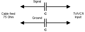
Принципиальная схема TV Antenna Ground Isolator - Eliminate Ground Loops- техническая информация, формулы расчета, описание
| Навигатор: QRZ.RU > Радиолюбительские справочники > Справочник компьютерного инженера |
TV Antenna Ground Isolator - Eliminate Ground Loops
This is a pretty simple circuit suitable for reducing/eliminating ground loops in home A/V systems caused by the ground return in the antenna cable. If you experience a 50/60Hz humming that disappears when you unplug the antenna cable to your VCR/TV then you have a ground loop and this is the remedy.
This circuit has only been tested with a strong antenna signal (as in cable TV feed or central antenna system), it might not be usable when the antenna cable is directly connected to an antenna far away from a TV station.

C=0.01uF ceramic disc capacitors, rated 200VAC or more
Remember that the key purpose of this excercise is to obtain isolation, if you use a metal case then make sure that you only connect one of the antenna cable shields to the case. After completing the circuit, verify the isolation with an ohm meter.
Keep the cable length as short as possible, especially on the "TV/VCR" side. This minimizes the induced power-line noise.
If the attenuation of the circuit is to high (ie. you get "snowy" picture) then you can try to replace both capacitors with higher value ones. It is important that both capacitors are replaced in order to maintain a balance in signal and return path. If you can't get a good signal then you'll probably have to use an (expensive) balun based isolator.
| Contributor: |
Niklas
Edmundsson Tomas Цgren |
| Source: | Ground Loops (or "Let Me Hum a Few Bars...") |
Информация предоставлена справочником The Hardware Book Team 1996-2004.
| Навигатор: QRZ.RU > Радиолюбительские справочники > Справочник компьютерного инженера |