Icom IC-751 RAM reprogramming IC751 re-programming
Icom IC-751 RAM re programming
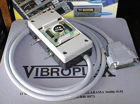
Download all text in MS Word file English translate by Nazario Culanag Jr. DU1QZC [du1qzc (at) yahoo.com] Dear colleagues! The text of article has been translated carelessly. Please if you will notice mistakes - write to me the correct text on email admin dog qrz dot ru. 73's UA9OTY Part 1IntroductionTen years ago, in 1991, I obtained my first all-transistor transceiver Icom-751 from one my very good familiar of Germany. Up to this moment I worked as the engineer- electronics specialist and the repairman of the radio systems of more than 15 years and it already had some experience of rotation with transceivers Ic-735 and Ts-440s during my trips to Sweden and Germany . First of all I included transceiver and it delighted in by its work during several it was hour. Everything, it seemed, functioned normally. To me was pleased both half-duplex and work from the pedal in the telegraphic regime, when operator has the capability transferring, to listen to in the pauses of his transfer and here to pass into the usual regime, having simply harvested to the pedal at the necessary moment. Earlier I used the same approach with the construction of the home-made transverter, which worked with R -250M2. Then I was switched to another band. To me was not immediately pleased used by designer sufficiently foolish ergonomics of double action, i.e., pushing of knob, and then the turning of the tuning knob of apparatus for changing the range. However, I properly was worried, when, being located to 14025.0 and changing range, I saw on the scale incomprehensible 21049.4 kHz! Already having an experience with the transceivers, mentioned above, including the apparatuses of approximately the same class - 735 and 745, I was convinced that I must prove to be after the change of range to 21025, 28025 and so on. But mysterious 049.4 as before remained on the scale! I turned off transceiver, waited three minutes, then was again included it. Strange defect was present. Those of the readers, who although once read Murphy's laws, must know that no one immediately reads instruction, encountering problems. Yes even Murphy's itself recommends the reading them only when it ceases to work absolutely all. So I honestly continued further completely in accordance with old Murphy's laws. Observing the strange transition point with the band selection, which by no means could not be explained from the position of the common sense (I he forgot about one - programmers in firm ICOM generally we could ever not be wireless enthusiasts), I solved, that some one of CMOS IS, which are been located inside, it was defective. Before the fact in me was sufficiently "pleasant" long-term practice with Ukrainian CMOS IS of the production of Vinnitsa plant (well this trash, 4 to you I will report!), those with especially subjected to the effect of the fastening, when in IS occurs the local breakdown of CMOS- structures, it begins to consume high current, strongly it nagrevayetsya and it does not function, in full or in part, as it is assumed to it. I opened schematic diagrams, very rapidly revealed small RAM on the pay of processor even it defined, that IS RAM was executed exactly on the CMOS- technology (analog of our K537RU14, which can be here used). Since RAM was energy-dependent, on the shawl was present small 3 v lithium small battery with size coin, preserving contained IS during turning offs of nourishment. 4 he already knew that turning off of nourishment with defective CMOS IS must end the begun effect of fastening and at the same time clean contained IS. Certainly, I was confident, that in RAM must remain only the frequencies of the channels of memory and other current information of processor (stack, register records) - exactly as in those transceivers, with which 4 already dealt. Therefore 4 completely it did not fear, what these data propadut - you will think, will introduce the channels of memory again... I boldly it took out to shawl RAM it unsoldered small battery by several minutes, sufficient, in order to unblock IS, which fell into the nonstandard regime. As unpleasantly I was struck, after seeing disorderly rubbish from the numbers on the scale, when I again included transceiver! Time arrived to read contrary operating instructions. O, what fool I was! What idiots these yaposhki!!! What feature they pushed the control codes of processor in RAM!!! - I was scolded as medical student in M. tven's short story. Entered wife it was any, UA1OSA, and I shared with it with last news, that 4 recently broken our expensive transceiver. It is any it presented to me the unforgettable view and, neither speaking nor word, it left. I set aside the unhappy ICOM to the side and erected in its place old, accurate, and, that the most valuable, absolutely non-RAM YAESU FTdx505 in order to rather call friends to the aid. Rapidly it answered my desperate khemskiy call Rune, SM0COP. It acquired new to shawl for 50 dollars and simply presented it to me. As reciprocal gift, I sent away to it very first normal Soviet calllbook - the large heavy book weighing of kilogram or near that. After the years, many our wireless enthusiasts burn into the same Japanese trap, as 4. And they all were forced to spend from 70 to 100 dollars in order to purchase and to obtain to shawl RAM from ICOM directly to their addresses. Become aware of tagretPurpose is realized it went time, and 4 began to think about the deadline of service my new by that presented Rune shawls and small batteries. Firm guaranteed only five years, but the periods of refusals can be and less... by that time 4 it already mastered rather well PiSishnye computers and was user during more than decades. Previously we all in USSR made computers themselves, as the reader, probably remembers, and my son, and 4 itself they were not exception. In the number of other we repeated famous RK-86 on i8080 processor as early as 1987 and she was about capable with the ease of programming both CMOS RAM and PROM with UV erasure. The computational power of any IBM PC in comparison with 86-RK made it possible to make this with tiny IS RAM of the transceiver simply of game. Unfortunately, i'm not he was programmer and did not know neither assembler nor high-level languages of programmings, for example - C++ or Pascal, which could be used here. After I shared in ether with its considerations with the "king of soldering iron" RU3XS, by Sergey, according to his recommendation I was turned to other to Sergey, RW3XA, who proved to be not only excellent DX operator, but also outstanding programmer and most experienced electronics specialist- experimenter. And to my enthusiasm, it had the electronic addresses of the mail both of the house and on the work. Thus, it became the co-author of this article. The use of the scanner and Internet made it possible to complete the rapid exchange of diagrams and of the ideas between UA1OSM and RW3XA. And here, three months later from that moment, as task it was set, Sergey sent communication to me, that the programmer already functions, and program is written also. Sergey up to that moment not had either transceiver ICOM, or the very shawls RAM, but it had a listing of sewn in RAM manager of program, and also a schematic of the firm programmer EX-428 of firm ICOM, the very shawls RAM and pays of the processor of transceiver - everything that 4 I could obtain from the different associates ether each in these years. Sergey prepared the mock-up of the programmer, which successfully worked with his 486- m, and, similarly, could work with any IBM - although 1980 of release. After obtaining of glad news and diagram with the program from Sergey, I prepared the suitable to the operation working version of programmer for the already present shawls RAM. However, it also worked well after its first switching on. Way barriersObstacles on the way several words here must be said about firm ICOM, from the point of view of responsibility for their production and its relations with the user. This firm is the best producer of amateurish and many other technology for the long years. And is simultaneously enemy the number of 1 wireless enthusiasts with piarovskikh respect to the type "firm-client". The policy of firm, approved by its headquarters, is very unfriendly, aggressive- self-reliantly on -samurai pumped, it denies any contacts, opinions, councils and other attempts at the feedback from the client to the firm. It sometimes seems that the firm is not simply interested in an improvement in its production, which refers to wireless enthusiasts. Complete opposition to this policy is the firm policy YAESU and Ten-tech usa . These firms always of friendly are opened to wireless enthusiast. So that if equipment ICOM would be only worse, 4 never it began not only it to acquire, but also to generally have any relation with this "supplier". It is understandable that any of the wireless enthusiasts, it goes without saying, never would obtain from the firm the codes of processor, internal soft, and so on for this domestic experimentation - R&D, such as we ventured with Sergey, for any of their articles - even it "19 centuries" and with the centenary beard! The European and American branches of firm, however, proved to be friendlier and they granted a certain information. This explainable - Europeans almost everywhere there work and Americans - normal people, without the strange conceit of headquarters ICOM, equivalent to conceit Napoleon Bonaparte. Thus, it was possible to obtain the codes RAM for the usual and improved version firmware 751 apparatuses. The reader, possibly, will say here that completely superfluously to be turned into the firm, when it is possible simply to rewrite the codes from the yet not devastated pay RAM, and this will be correctly - now, when there is a finished programmer! But since the task of the copying of the codes from one side, and the creation of programmer by pillar - with another, are approximately equivalent on labor expenses, everything becomes in its places - we created article, having as the model almost anything, except our large desire. Several words about the firm programmer ??- 428 of firm herself. This device was created by ICOM for the reprogramming of pays RAM under the conditions of the branches of worldwide support . These are the expensive instrument, prepared on the base of processor 8085, PROM, by analogous UV PROM 573RF2, its own soft, find in this IS, and socket for one additional RF2, from which the program for the copying was taken. I.e., programs are stored in RF PROM, specific IS for the specific model it is necessary to put into the panel, then to put to shawl RAM in the place for its programming, which is two rows of contact needles, then to include programmer and to produce readout from PROM in the memory of processor, and then - record in RAM. The indication of the fulfillment of the operations of reading and writing occurs on liquid-crystal indicator or light-emitting diode signal panel, set into into instrument itself. I evaluate the cost of ?? -YA28 itself, approximately equal cost of the transceiver, with which the discussion deals, so that does not have sense whatever to acquire this device the firm, even if it will agree it to sell. - I is confident moreover, that also would here follow the refusal, in view hostile- oriented policy IccOM'a with respect to the wireless enthusiasts. Mechanic descriptions and purchased devicesWhat does represent programmer outside? This is the small plastic box of two halves, fastened along the angles by four small screws - samorezami. Inside is located the printed-circuit board, prepared on Vol. n. "assembly mole-rat" - to the network of openings with a step of 2.5 mm. of course it is possible to eliminate pay of very. On the pay find two IS and landing needles for shawls RAM. The pay of programmer is pressed between the plastic halves of box. In the upper part of the box is cut out the window for the insert shawls RAM. Two IS of 555 series are used, for the inexperienced amateurs it is possible to recommend with the repetition to use sockets for IS, although this is not compulsory. Besides two STTL IS and sockets are necessary two rows of the contact needles, which can be taken from any old and unfit PC computer card, two light-emitting diodes also of resistor, one capacitor even two miniature toggle switches. The scarcest component is the piece of computer cable for printer IBM PC, the so-called cable of parallel port with the joint of the type of Centronics; moreover the presence of last joint is not compulsory. If the reader has available the entire intact cable or it will decide him to purchase, then it is better to purchase the mating part of the joint Centronics for the installation on the box in order to preserve cable for the daily work with the computer and the printer. If the joint Of Centronics is absent, or it is damaged - it it is necessary to withdraw entirely, and then to embroider cable inside the box. Setting the mating part of the joint Centronics will somewhat increase the dimensions of your box. But it is also necessary to prepare the power unit, which would issue the stabilized voltage of +5 volts (not more than 5.5 and not less than 4.5!!!) with the current not less than 50 mA. The author used the existing power unit of the portable external computer accumulator of Bernoulli - 100 mb. ZIP-drive firm IOMEGA, which widespread in Russia. Block issues plus of 5 volts with the current to 1 A, which is ideal for this device, those more you not will exploit its each day. For the connection of nourishment is necessary the corresponding joint (as on the transistor radio receiver) or the pair of clamps. Present version works under Windows in window DOS. Programmer is necessary for the following transceivers of firm ICOM, designed with the application RAM: Models 740, 745, 751, 751?, 271?, 271?, 471?, 471?, 1271, 761, receive R-71. of the diagram of RAM board have two interchangeable versions. Contained RAM (codes) they befit only for the concrete model of apparatus and they are not interchanged. Part I prepared for the publication on the site S. Matveyev, ua1osm (at) arh.ru Part 2Introductionit is immediately necessary to note that I am not worshipper ICOM. So already it was formed, that that technology ICOM and KENWOOD, with which for me it was necessary to encounter, did not leave proper impression. As a result this affected also selection HF and VHF transceivers for itself in favor YAESU. On the small nuance with the replacement of small battery in transceiver ICOM 4 already somehow it heard, but perceived this simply as the concrete result of careless handling with "thin" Japanese electronics. There was how my surprise, when to me turned himself Sergey UA1OSM and he described about its problem with Ic-751. On that which occurs, such occurs not too and it is rare, and it is far from in one model of transceivers ICOM. And, that most important, possibly entirely not through the fault of user, but through the fault of developers ICOM. I.e. through several years of operation small battery is discharged and data in RAM disappear, but without these data transceiver will not earn even with the new small battery... Certainly, you can object, which when these transceivers were developed, yet not there were such concepts as FLASH, EEPROM and the like. but, since as a result of the discharge of lithium battery (even through several years) transceiver becomes absolutely inefficient, then producer was obligated to think about his clients and to provide something in order to exclude this situation. Simplest to place the second holder for the battery and in the operating instructions the need for the installation of new battery (and only after this removal of old), for example, every 4 years... At least so would be honest and, most importantly, it is more reliable. On the whole - puncture. But possibly, this was the simply long-term concern about its service centers. Yes, technologies are improved also in the contemporary transceivers of this problem no longer there exists, but on how much already years old Japanese transceivers work, and still they will be able! If by them a little soak. That do not say, but nevertheless fine people the Japanese, they know how to make electronics and transceivers in particular. Thus, in the process of considering the problem with UA1OSM we came to the conclusion that it is good to make a programmer for Ram-unit module. Good by this time Sergey already somehow procured the selection of piercings RAM for several models of transceivers ICOM. I.e. it was that write and it was necessary still than, i.e., it was necessary to make an electronic part of the programmer and to write controlling program for it. Here I astonished second time, occurs UA1OSM it has already sufficiently long ago discussed this problem in ether and in this time to it not who it fell (or at least it did not respond) from those, who could solve it. Apparently, to Sergey simply it did not transport, or it there did not search for. 4, for example, amateur CW and DX, and almost always in ether (if it is free from the work, the children and the wife), although me and not frequently audibly: -) . On the whole, the idea with the programmer me interested, and, first of all in the fact that as a result must come out a device sufficient simple in the repetition, with the aid of which it is possible "to revive" or to prolong life some IccOM- OV. On the whole, it was necessary to be decided and to find several days that to tightly study the embodiment of idea into the life. In principle, this programmer (Ex-428) has long ago existed, but, as it is described above, price makes with its inaccessible. Especially as programmer is necessary one time in several years. By the way, this article is written precisely for those, to whom it is interesting not only "to drive" on the transceiver, but still also "to rinse the brains" this transceiver. Otherwise, ~100$ for the new RAM module plus several months of expectation there are no problems... Schematic diagramFor programming of the module it is necessary of 4 bidirectional and 12 output signals; therefore the most rational solution was the use of a parallel (LPT) port of computer. Moreover with the development was considered the possibility of the works on any computer, including XT and 286, in which were used unidirectional LPT ports. Programmer is executed on two microcircuits, the first (K1533IR23 or 74ALS374 ) is used for the catch of address, the second ( K1533AP4 or 74ALS241 ) for multiplexing of the direction of data bus with write/read. For the nourishment of microcircuits is necessary any power unit with the output stabilized voltage of +shchV and the current 50-100 mA. For example two batteries on ya.shchV (for the hour of work it will be sufficient, but more and not must) + stabilizer 78L05 or power unit from the modem + 78L05.
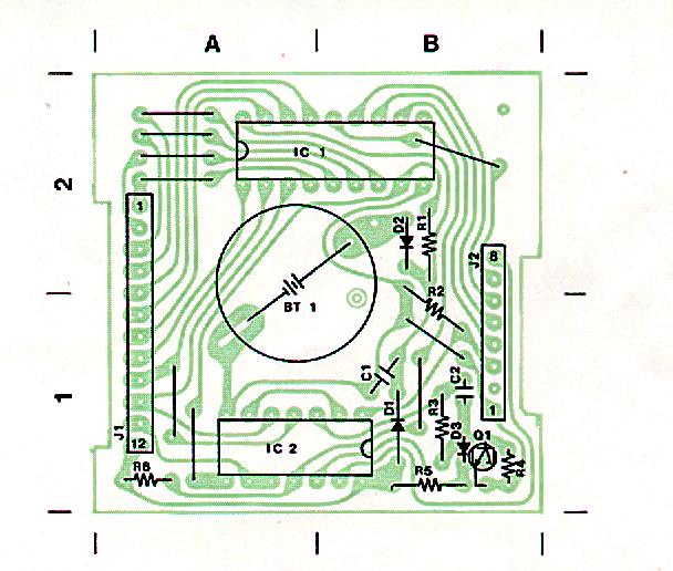
Pic.1 Schematic diagram Switch "Lock-Pgm" is intended for the apparatus blocking of module from the random record with its installation or extraction from the programmer and respectively for the start of module to the period of work with the program. By other words to transfer switch into the position "PGM" is necessary only after the starting of program and with the already established module. But before the output from the program or before the extraction of module switch must be set to the position "LOCK". The fact is that the necessary state of the lines of port LPT is established only on the period of the work of program, all the remaining time by these lines govern BIOS, the system or other programs, which a concept do not have about the programmer for RAM modules. But to what this can lead you and themselves you surmise... SoftwareProgram for programming RAM of modules (icom_.pgm.exe) is written for DOS, i.e., for the programming will approach even XT, but, nevertheless, it excellently works under Windows and is used direct access to registers LPT of port, passing system drivers. After starting reveals the prompt, that it is possible to unblock module (regime "PGM"), if it is already established. In the program are realized only two functions - reading (Read RAM) and records with the checking (Write/Verify RAM). With the pressure of key "R" (reading) inquires the name of the file, in which there will be preserved current contents of the memory of module. After the introduction of the name of file reading and retention of data into the file begins. If the name of file is not assigned, then contents of memory only will reflect on the screen. On the key "W" inquires the name of the initial file, the contained which it will be recorded into the memory of module. To program icom_.pgm.exe are applied the files with the data for the modules of several types of transceivers. If you do not have anything better, then try them. But if you want to reprogram the module of working transceiver by new piercing, then it is better to first read contents of module and to preserve him into the file, then you always be able to return module into the initial state! Try to store such files in the special catalog in order to exclude the loss of file with reading with the retention into the file. In the regime of record checks for itself reading for each byte. If the recorded byte does not coincide with schitannym, then reveals communication about the error with the indication of the address of the written and schitannogo byte. On leaving from the program reveals the communication, that it is necessary to block module, for this it is necessary switch to transfer into the position "LOCK". To take out module from the programmer is possible only in the position "LOCK", also, after turning off of the nourishment of programmer. ConclusionWith the development of the apparatus and program part of the programmer i not had real Ram-unit module. For the fixing it was necessary to make its analog on KRSHCHE"ruy0 (KRSHCHE"ruyya it did not be located), since with respect to characteristics they practically identical and are characterized by only organization. UA1OSM repeated diagram, tested with the present module and... (here I it astonished third time)... everything immediately earned, including transceiver Ic-751! I hope, in you also everything will come out. The archive of all is file for the programmer - icom-pgm.zip (52kb) Sergey Satyr, RW3XA.
Description of the very diagram and software will be done below by Serge Satyr, RW3XA.
Alternative problem decision by WA9FVP:This information will complement the product review that was You can also view the board on our WEB page http://www.ameritech.net/users/willco788/my1.htm ATTENTION ICOM OWNERS, YOUR MEMORY CAN FAIL!In the mid 80's Icom introduced the IC-745 transceiver and R71 short
MORE MEMORIES THAN YOU'LL EVER NEED!The Willco ICM-1024B was originally designed for the R71 receiver and
EASY TO INSTALLFor Ham radio applications you probably don't need 1024 memories and
HERE'S HOW IT WORKSEven with Icom's IC-EX310 speech option installed, the SPEECH button EXTENDED FREQUENCIESIcom used the RAM based design so that they can easily modify the ONE SIZE FITS ALL!By simply adding a jumper, the ICM-1024 can be installed in an R71, ---------------------------------------------------------------- http://www.ameritech.net/users/willco788/my1.htm
|